How to simulate mobile ad hoc networks using VNUML
|
 |
| Introduction | |
|
The aim of this brief report is to show how the VNUML parser and User Mode Linux can be used for simulating mobile ad hoc networks (MANETs). Many simulators for such environments already exist in response to the problem of developing transport level protocols in such environments. The main drawback of these simulators relies in the fact that all of them force the developer to design and write the code in a simulator-dependent way. This last problem becomes a big issue once the developer is willing not to evaluate a distributed algorithm, but to test an entire application specifically designed for mobile ad hoc networks. In this last scenario in fact, the developer's desire is to test the same code that will be deployed on actual devices. The process of separately developing a simulation code and the actual application code is useless since the two are written quite always in different programming languages and use completely different abstractions level and engineering requirements. In the rest of the report we will show how this last testing process can be carried out in a very simple way using the VNUML parser and User Mode Linux. These very powerful tools allowed us to test in a MANET-like virtual scenario the same code that we will deploy on actual devices. In particular, the procedures and scenario setup we will show have been used for testing a publish-subscribe middleware specifically designed for mobile ad hoc networks. However, what we will describe in the rest of the document can be easily adopted without changes for testing any distributed application for MANETs. Our approach obviosly makes sense only if the application we are willing to test is not designed for using any routing algorithm or underlying tranport layer such as AODV or TORA. These lasts protocols are in fact specifically designed for MANETs with the goal of hiding to the application level all the details regarding node mobility: if you are planning to use such protocols, then the approach we are going to expose is obviously pointless. |
|
| Scenario design and setup | |
|
Mobile ad hoc networks can be characterized along several dimensions and offer several unique characteristics that are out of the scope of this document. What we should keep in mind for our main purpose can be summarized as follows:
Having in front all these characteristics, one can easily observe that the key point of simulating such a scenario for testing purposes resides in the ability of creating and destroying communication links between any pair of mobile hosts. This last issue is what vnumlparser and UML can solve in a very simple way. What we have done for achieving this goal is to simply define a scenario with N UML processes in the role of mobile hosts and N*(N-1)/2 UML processes in the role of communication links. These last UML hosts will be called from now on "link hosts". Each link host plays the role of a wireless link acting as an IP router between two UML hosts in the role of mobile hosts. With our scenario setup, one can easily simulate the presence of a link between two mobile hosts by activating the IP forwarding rule on a certain link host, while the absence of a link can be simulated in the same easy way by deactivating the same IP forwarding rule. A single command can turn on or off a link, simulating when two mobile hosts are close enough to hear each other or not. With the right combination of links turned on or off one can simulate networks partitions or any initial network topology. By turning on and off the links while the application evolves one can simulate node mobility and test how the application under examination reacts to such network topology changes. A simple example of a system composed of 4 mobile hosts and the necessary link hosts can be found in the following XML file. For keeping the things manageable as the number of mobile hosts grows, a suitable IP addressing scheme has been defined in the scenario definition file. The i-th mobile host is assigned an IPv4 address like 10.0.i.i, while each link host is assigned an IPv4 address of type 10.0.i.j and 10.0.i.j (depending on which network interface one considers), where i and j are the two mobile hosts the link host can connect.
<?xml version="1.0" encoding="UTF-8"?>
<!DOCTYPE vnuml SYSTEM "/usr/share/xml/vnuml/vnuml.dtd">
<vnuml>
  <global>
    <version>1.7</version>
    <simulation_name>manet5</simulation_name>
    <ssh_key>/root/.ssh/identity.pub</ssh_key>
    <automac/>
    <vm_mgmt type="private" network="10.250.0.0" mask="24">
       <host_mapping/>
    </vm_mgmt>
    <vm_defaults>
       <filesystem type="cow">/usr/share/vnuml/filesystems/root_fs_tutorial</filesystem>
       <kernel>/usr/share/vnuml/kernels/linux</kernel>
       <console id="0">xterm</console>
    </vm_defaults>
  </global>
  <net name="Net1" mode="uml_switch"/>
  <net name="Net2" mode="uml_switch"/>
  <net name="Net3" mode="uml_switch"/>
  <net name="Net4" mode="uml_switch"/>
  <vm name="uml1">
    <mem>50M</mem>
    <if id="1" net="Net1">
      <ipv4>10.0.1.1</ipv4>
    </if>
    <route type="ipv4" gw="10.0.1.2">10.0.2.0/24</route>
    <route type="ipv4" gw="10.0.1.3">10.0.3.0/24</route>
    <route type="ipv4" gw="10.0.1.4">default</route>
  </vm>
  <vm name="uml2">
    <if id="1" net="Net2">
      <ipv4>10.0.2.2</ipv4>
    </if>
    <route type="ipv4" gw="10.0.2.1">10.0.1.0/24</route>
    <route type="ipv4" gw="10.0.2.3">10.0.3.0/24</route>
    <route type="ipv4" gw="10.0.2.4">default</route>
  </vm>
  <vm name="uml3">
    <if id="1" net="Net3">
      <ipv4>10.0.3.3</ipv4>
    </if>
    <route type="ipv4" gw="10.0.3.1">10.0.1.0/24</route>
    <route type="ipv4" gw="10.0.3.2">10.0.2.0/24</route>
    <route type="ipv4" gw="10.0.3.4">default</route>
  </vm>
  <vm name="uml4">
    <if id="1" net="Net4">
      <ipv4>10.0.4.4</ipv4>
    </if>
    <route type="ipv4" gw="10.0.4.3">10.0.3.0/24</route>
    <route type="ipv4" gw="10.0.4.2">10.0.2.0/24</route>
    <route type="ipv4" gw="10.0.4.1">default</route>
  </vm>
  <vm name="uml1-2">
    <if id="1" net="Net1">
      <ipv4>10.0.1.2</ipv4>
    </if>
    <if id="2" net="Net2">
      <ipv4>10.0.2.1</ipv4>
    </if>
    <route type="ipv4" gw="10.0.2.1">default</route>
    <forwarding type="ipv4" />
  </vm>
  <vm name="uml1-3">
    <if id="1" net="Net1">
      <ipv4>10.0.1.3</ipv4>
    </if>
    <if id="2" net="Net3">
      <ipv4>10.0.3.1</ipv4>
    </if>
    <route type="ipv4" gw="10.0.3.1">default</route>
    <forwarding type="ipv4" />
  </vm>
  <vm name="uml1-4">
    <if id="1" net="Net1">
      <ipv4>10.0.1.4</ipv4>
    </if>
    <if id="2" net="Net4">
      <ipv4>10.0.4.1</ipv4>
    </if>
    <route type="ipv4" gw="10.0.4.1">default</route>
    <forwarding type="ipv4" />
  </vm>
  <vm name="uml2-3">
    <if id="1" net="Net2">
      <ipv4>10.0.2.3</ipv4>
    </if>
    <if id="2" net="Net3">
      <ipv4>10.0.3.2</ipv4>
    </if>
    <route type="ipv4" gw="10.0.3.2">default</route>
    <forwarding type="ipv4" />
  </vm>
  <vm name="uml2-4">
    <if id="1" net="Net2">
      <ipv4>10.0.2.4</ipv4>
    </if>
    <if id="2" net="Net4">
      <ipv4>10.0.4.2</ipv4>
    </if>
    <route type="ipv4" gw="10.0.4.2">default</route>
    <forwarding type="ipv4" />
  </vm>
  <vm name="uml3-4">
    <if id="1" net="Net3">
      <ipv4>10.0.3.4</ipv4>
    </if>
    <if id="2" net="Net4">
      <ipv4>10.0.4.3</ipv4>
    </if>
    <route type="ipv4" gw="10.0.4.3">default</route>
    <forwarding type="ipv4" />
  </vm>
</vnuml>
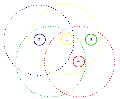
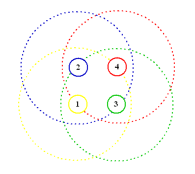
The VNUML specification file can be download from here (there is also a old 1.3 based version). The scenario defined by the previous XML file can be observed from two different point of views corresponding to the two different abstraction levels: we can consider the real (fixed) network topology that the vnumlparser build when the simulation scenario is setup or the upper level wireless network topology we are going to use for testing applications on MANET. The following two figures illustrate these two standpoints: the first figure shows the fixed network topology with hosts (circles) and routers (squares) connected as per our definition file; the second figure shows our upper layer wireless network where routers are hidden in the role of wireless links, the particular network configuration shown in the picture corresponds to the situation where one has all the link hosts with the IP forwarding capabilities turned on, i.e. all the mobile hosts are able to hear each other. 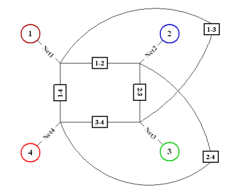
|
|
| Simulation approaches | |
|
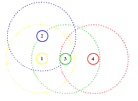
Once the testbed is setup, one can approach the testing process in two different and orthogonal ways depending on the particular nature of the code. If the application we are willing to test exhibits a totally predictable behavior, then the best choice we can make is to setup a predefined sequence of topological changes, launch the application on the mobile hosts, trace in some way the application evolution and then collect the results once the simulation has ended. These results will be checked against what we expect from our application. In practice, this can be done with VNUML by adding suitable tags in the definition file describing the sequence of topological changes we desire. For instance, let us assume we want to start a system with 4 mobile nodes that initially exhibit a complete connectivity, after 30 seconds we want a first link break that poses node 4 outside the range of node 1 and node 2 and after 60 seconds we want node 2 able to communicate only with node 1 while the link between 4 and 1 reappers. This three-step sequence corresponds to the following three topologies for t=0s, t=30s and t=60s.
To achieve this, one has to simpy add the following tags in the definition file for all the link hosts actively involved in this particular sequence. For example, uml1-4 will include the following:
<vm name="uml1-4"> ... <exec seq="start" type="verbatim">sleep 30s</exec> <exec seq="start" type="verbatim">echo 0 > /proc/sys/net/ipv4/ip_forward</exec> <exec seq="start" type="verbatim">sleep 60s</exec> <exec seq="start" type="verbatim">echo 1 > /proc/sys/net/ipv4/ip_forward</exec> </vm>so for uml2-4: <vm name="uml2-4"> ... <exec seq="start" type="verbatim">sleep 30s</exec> <exec seq="start" type="verbatim">echo 0 > /proc/sys/net/ipv4/ip_forward</exec> </vm>and for uml2-3: <vm name="uml2-3"> ... <exec seq="start" type="verbatim">sleep 60s</exec> <exec seq="start" type="verbatim">echo 0 > /proc/sys/net/ipv4/ip_forward</exec> </vm>Furthermore, all mobile hosts will simply include a single command to start the application we want to test: <vm name="umlX"> ... The second approach is more suited to those scenarios where the application behavior is not completely predicatable and hence the developer could think about rearranging the topology depending on how the application evolves. This situations be simply managed opening a ssh session towards each link host and one or more mobile hosts. While the application evolves we can create on-fly those topologies that could be critical for our application by directly interacting with the virtual machines. |
|
| Further developments | |
|
With the previous considerations and scenario setup one can successfully simulate an arbitrary MANET environment having only the capabilities of the real host used for running the simulation as boundaries, but we can go even further in having a more precise simulation of wireless communications. What we have done in the previous paragraph allowed us to turn on or off a wireless link. In the real life, however, wireless links not only appear and disappear, but also exhibits a set of problems related to the non-perfect nature of the transmission medium. Two examples are messages delays and lost packets. We can simulate such characteristics of wireless communications by hacking the Linux kernel in a relative simple way. Luckily, what is important for us is entirely contained in a single brief C file of the Linux kernel source named ip_forward.c. We can simulate packet dropping by adding a few lines of code before the last instruction that would send out the forwarded packet. For instance, we can extract a pseudo-random number and define a given probability that the packet will be dropped. The same also applies in case we want to simulate a given message delay: all we have to do is to put a wait() call in any point of the function named ip_forward(). Once we have done that, we will have to patch the kernel for using the compiled image as UML and to substitute it in place of the kernel we previously used on link hosts. |
|
| Final considerations | |
|
User Mode Linux and the VNUML parser can be invaluable tools for testing applications in MANETs environments. However, we should always keep in mind that such tools can only be used for testing purposes and not for evaluating the performances of our application. In other words, what we can check is the correctness of the code we have written, not its performances. This is quite obvious since User Mode Linux was not intended for such purposes: UML processes are scheduled as user-space processes and no coordination layer for simulating concurrency in a precise or fine-grained way exists among them. A correct and reliable distributed application should work regardless of the concurrency relations among different hosts, therefore we can use UML for testing our code. The same does not hold when we want to evaluate the performances of our application, since the results we could obtain would be completely misleading. One could also argue that such testing approach does not scale very well. In our honest opinion this is not completely true: it does hold the fact that a system with N mobile hosts requires N+(N*(N-1)/2) UML processes, hence the simulation load grows as O(N^2). However, what each link host performs during the simulation is only to forward IP packets: a very simple procedure that does not pose on those hosts a sensible load. One could also compile a tailored linux kernel and a specific filesystem only for link hosts in order to keep the total load as low as possible. This is what we have done for our needs: with some fine grained tuning on kernels and filesystems (the boot phase can take much time if processes that are not stricly required are loaded at boot time on every machine) we succeeded in simulating a system with 8 mobile hosts (i.e. 36 UML processes) on a 1 Ghz machine with 1Gb Ram. |
|
|
|
|
