 At the point at which I needed to build an external antenna for
my modified Compaq WL100 card I was faced with many options.
Internet searches reveal many designs for this band,
some of which provide really good homebrew details and others
that left a little to the imagination!.
I was looking for a design that promised reasonable gain without
excessive size. The short backfire antenna is not a common antenna,
promised 14dBi and looked easy to build. Several designs were found
and analysed which did reveal a few discrepancies which seem now that
been resolved.
At the point at which I needed to build an external antenna for
my modified Compaq WL100 card I was faced with many options.
Internet searches reveal many designs for this band,
some of which provide really good homebrew details and others
that left a little to the imagination!.
I was looking for a design that promised reasonable gain without
excessive size. The short backfire antenna is not a common antenna,
promised 14dBi and looked easy to build. Several designs were found
and analysed which did reveal a few discrepancies which seem now that
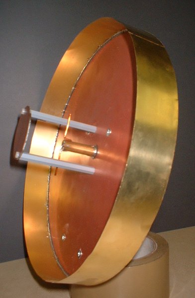
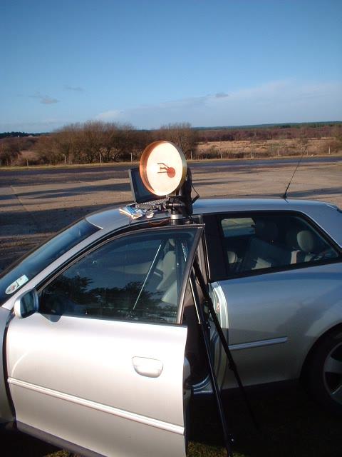
been resolved. A quick look at the finished antenna shows a 'cake tin' style base fed with a half wave dipole and sub-reflector.
Now for a few calculations and dimensions:
The centre of the 802.11b band is channel 8 at 2.447GHz which equates to a wavelength of 122.6mm
The 'cake tin' base is made from standard copper clad FR4 PCB material (any solderable sheet would do) and has a diameter of 2 Wavelengths or 245mm. I marked it out with a compass and then cut it with tin snips.
The height of the side of the 'cake tin' is a quarter wavelength or 30.6mm. I used brass shim cut and soldered to the PCB base on both sides for rigidity. (Allow that extra few mm of height)
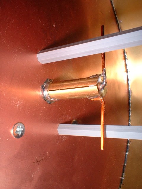
The driven element is probably the trickiest to make (see the closeup photo) as it requires you to select tubes of the correct diameter to achieve a 50Ohm impedance. I selected K & S metals tubing of 13/32" and 4mm tubing (Great mixture of units!) This gives the correct impedance according to the formula Z = 138 Log (D/d) where D is the inner diameter of the outer tube and d is the outer diameter of the inner tube!
The outer tube must have quarter wavelength slot cut into the dipole end as shown in the closeup photo. This I achieved by tightly rolling paper and pushing this plug into the end of the tube and then cutting across the tube (and paper) - This stops the tube deforming. Once the 30.6mm quarter wave slot has been cut it should be cleaned up with a needle file.
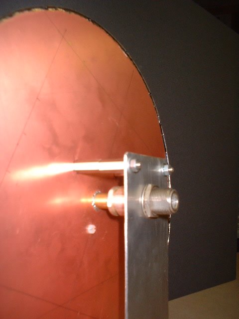
The non-slot end of the tube should be soldered into the top nut of an N connector - Either plug or socket as you prefer. I had a handful of N's to select from to get a nut with a good fit to the tube.
Next solder the N pin (or socket) to the end of the 4mm tubing and assemble the connector to get the correct length of the inner tubing - Then mark & cut so that the assembled connector has the inner and outer tubes flush for fitting the dipole elements. I also added a piece of PTFE from another N connector at the top of the slot to hold the inner tube in the centre of the outer tube and ease the soldering exercise.
Now it's time to fit the driven element to the 'cake tin'. I used a small piece of larger
tubing (7/16") which is a sliding fit over the 13/32" tubing. The larger tube is soldered flush with the front face of the antenna and allows the driven element to be finely tuned before finally soldering. (If you don't have the means to test the VSWR just solder the tube so that the slots are flush with the front face of the antenna)
Add two lengths of 1mm diameter wire to the slotted end as shown allowing little extra for tuning - I have ended up with a total end to end length of the dipole of 60.0mm
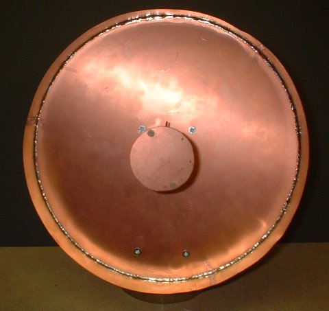
The next easy step is to add the sub-reflector. Another piece of PCB material diameter 49mm (0.4 wavelength) is fitted on two insulating pillars secured with M3 nylon screws. I spent some time fine tuning the position of this plate and ended up with a spacer length of 73mm. This doesn't tie up with the two designs referenced but does with a third article - What do you believe? This dimension seems to give a good match and maximum gain - See the 14Km path test article!
Now I've just described how I built my short backfire antenna but you should check out the article "Wlan antenna 2.4GHz Do-It-Yourself" by Martti Palomaki at http://www.saunalahti.f/~elepal/antenna1.html on which these notes are based. His article references a good design in 73 magazine October 1982 - "Try the GHz Getter" by John M. Franke WA4WDL.
The K & S brass tubing and shim I bought from The Model Shop (Newcastle) Ltd who have an excellent web site: http://www.model-material.com