LEarn from Video Extensive Real Atm Gigabit Experiment

LEarn from Video Extensive Real Atm Gigabit Experiment |
|
| LEVERAGE News No 2, April 1997 |
| Welcome | Co-ordinator | Pedagogical | InterACTS | Acronym key |
|
Technophile
The overall LEVERAGE architecture is distributed over three sites at Cambridge, Paris and Madrid. Nevertheless, each site needs to have its own network to allow local communication. These ATM islands may then be interconnected to provide the international interworking aspect of LEVERAGE. This article describes the network at the Cambridge site, which is now up and running; the second site will be installed later this year and the third site will follow next year. The figure below shows the LEVERAGE system, which may be seen as a combination of two parts:
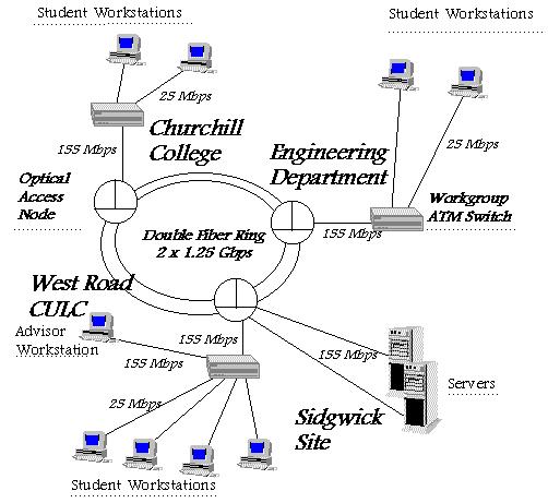 The LEVERAGE system architecture for the Cambridge trial The figure shows the LEVERAGE network which is installed at the Cambridge site. A high-speed optical network, using the fibres of the GRANTA backbone, connects the main sites, i.e. Sidgwick (University of Cambridge Language Centre), Engineering Department, and Churchill College - whereas West Road is accessed through the switch at Sidgwick. Note that the distances between the different sites vary from two to three kilometres, except between Sidgwick and West Road, where we have a distance of 150 metres. In order to achieve equal performance for every user of the system - and not to privilege the ones at Sidgwick - the servers are directly connected to the optical network, while all workstations (users and advisor) first access a workgroup switch. The types of physical interfaces used are OC-3 (Multimode fibre (MMF), 155Mbps) for the servers and the advisor workstation, whereas the student workstations have desktop ATM interfaces conforming to ATM Forum (Unshielded Twisted Pair (UTP)-3, 25Mbps). This is to comply with the interfaces provided by the optical access nodes and the workgroup ATM switches. The optical network is based on a Double Fibre Ring (DFR) architecture which transports ATM cells at a speed of 1.25 Gbps and features protection switching in order to increase the reliability of the system. The ASCOM Access Nodes (AAN) are used to access the optical network and thus to connect the sites with each other. The signalling protocol conforming to ATMF UNI 3.1 is supported; furthermore, a Ring Management System (RMS) provides the network management functionality. The workgroup ATM switches - ATM Ltd. VIRATA Switch - are equipped with twelve interfaces conforming to the ATM25 specification and an expansion module containing two OC-3 inter-faces, one of which is used to connect to an optical access node. At the Engineering Department site a STM-1 interface is required in order to access the European ATM pilot network through a University of Cambridge campus switch. Last but not least, one of the servers is also configured as a router and thus allows the access to the Cambridge University Data Network (CUDN) and the Internet. |
|
About LEVERAGE |
Conferences |
Deliverables |
Partners |
Press Archive |
Related Projects
LEVERAGE News 1 - Sept 96 | 2 - April 97 | 3 - Sept 97 | 4 - July 98 | 5 - Feb 99 |
|
LEVERAGE home page |
Last updated 1st June 1999 E-mail: leverage@cilt.org.uk |
 Antonio Seminara, research engineer at ASCOM Tech in Bern, Switzerland and leader of the LEVERAGE work package on networks gives an overview of the LEVERAGE system architecture